Practice portal › Current Electricity › Combination of Resistors
Asked in GUJCET 2017 · Symmetric and complex networks
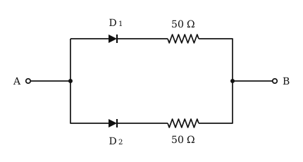
Idea: an ideal diode is a short circuit when forward biased and an open circuit when reverse biased.
In the figure both D₁ and D₂ point from A towards B, each in series with 50 Ω, and the two branches are in parallel.
(i) V_A>V_B: both diodes are forward biased and conduct.
The two 50 Ω branches are then in parallel: R=(50×50)/(50+50)=25 Ω.
(ii) V_B>V_A: both diodes are reverse biased and block, so no current flows between A and B: R=∞.
So the equivalent resistances are 25 Ω and ∞.
Reading this solution needs no sign-in. You only sign in to practise against the clock and keep your progress.
Practise this with a timer