Practice portal › Semiconductor Electronics › Digital Electronics and Logic Gates
Asked in NEET 2020 · Gate combinations and truth tables
| A | B | Y |
|---|---|---|
| 0 | 0 | 0 |
| 0 | 1 | 1 |
| 1 | 0 | 1 |
| 1 | 1 | 1 |
| A | B | Y |
|---|---|---|
| 0 | 0 | 1 |
| 0 | 1 | 1 |
| 1 | 0 | 1 |
| 1 | 1 | 0 |
| A | B | Y |
|---|---|---|
| 0 | 0 | 1 |
| 0 | 1 | 0 |
| 1 | 0 | 0 |
| 1 | 1 | 0 |
| A | B | Y |
|---|---|---|
| 0 | 0 | 0 |
| 0 | 1 | 0 |
| 1 | 0 | 0 |
| 1 | 1 | 1 |
| A | B | Y |
|---|---|---|
| 0 | 0 | 0 |
| 0 | 1 | 0 |
| 1 | 0 | 0 |
| 1 | 1 | 1 |
Idea: reduce the circuit to an expression, then fill the table in.
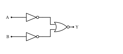
The inverters give A and B, and the NOR gives Y=A+B.
De Morgan's law turns that into Y=A· B.
So the output is high only when both inputs are high: 00→0, 01→0, 10→0, 11→1.
That is the fourth table.
Reading this solution needs no sign-in. You only sign in to practise against the clock and keep your progress.
Practise this with a timer