Practice portal › Semiconductor Electronics › Digital Electronics and Logic Gates
Asked in NEET 2021 · Waveforms, switches and diode gates
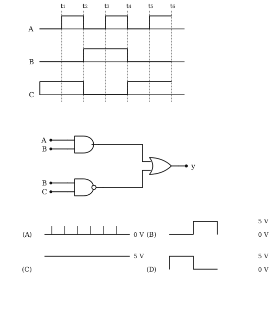
Idea: write the output as an expression, then look at what the waveforms make each term do.
The upper AND gives A· B and the lower NAND gives B· C, and the OR adds them: y=A· B+B· C.
Read B and C off the waveforms: whenever B is high C is low, and whenever B is low C is high. They are complements.
So B· C=0 at every instant, and B· C=1 at every instant.
A logical sum with a term stuck at 1 is itself stuck at 1, whatever A· B does.
The output stays high throughout, at 5 V, which is Graph (C).
Reading this solution needs no sign-in. You only sign in to practise against the clock and keep your progress.
Practise this with a timer