Practice portal › Semiconductor Electronics › Digital Electronics and Logic Gates

Choose the correct logic circuit for the given truth table having inputs A and B. Truth table (A, B, Y): 0 0 0; 0 1 0; 1 0 1; 1 1 1. [Figure: four circuits, each ending in an AND gate. (a) A and B go to an OR gate; the OR output and A (by a separate wire) go to the AND gate. (b) Same, but the separate A wire passes through a NOT gate. (c) Same as (a), but the OR output passes through a NOT gate. (d) A and B go to an OR gate; the OR output and B go to the AND gate.]

Asked in JEE Main 3rd April 1st Shift 2025 · Gate combinations and truth tables
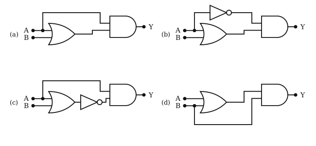
Figure: Gate combinations and truth tables
Answer: (1) Y=A·(A+B)

Step-by-step solution

From the table, Y copies A in every row, so Y=A.

Circuit (a): Y=A(A+B)=A by absorption.

Why the other options are wrong

More Digital Electronics and Logic Gates questionsAll Digital Electronics and Logic Gates questions →

Reading this solution needs no sign-in. You only sign in to practise against the clock and keep your progress.

Practise this with a timer