Practice portal › Semiconductor Electronics › Digital Electronics and Logic Gates
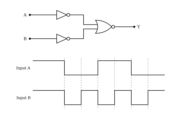
The logic circuit shown below has the input waveforms A and B as shown. Pick out the correct output waveform. [Figure: A and B each pass through a NOT gate into a NOR gate giving Y. Over six intervals, A: 1, 0, 0, 1, 1, 0 and B: 1, 0, 1, 0, 1, 0, with B returning to 1 after the last dashed line. Options: (a) 1, 0, 0, 0, 1, 0; (b) 1, 0, 1, 1, 0, 1; (c) 0, 1, 1, 0, 1, 0; (d) 1, 0, 0, 1, 0, 1.]
Asked in JEE Main 2009 · Waveforms, switches and diode gates
- (1) 1, 0, 0, 0, 1, 0
- (2) 1, 0, 1, 1, 0, 1
- (3) 0, 1, 1, 0, 1, 0
- (4) 1, 0, 0, 1, 0, 1
Answer: (1) 1, 0, 0, 0, 1, 0
Step-by-step solution
Y=A+B=AB
AB=1 only in intervals 1 and 5.
Output: 1, 0, 0, 0, 1, 0.
Why the other options are wrong
- (2) Not AND of the inputs.
- (3) Not AND of the inputs.
- (4) Not AND of the inputs.
Reading this solution needs no sign-in. You only sign in to practise against the clock and keep your progress.
Practise this with a timer