Practice portal › Semiconductor Electronics › Digital Electronics and Logic Gates
Asked in JEE Main 12th Jan 1st Shift 2019 · Gate combinations and truth tables
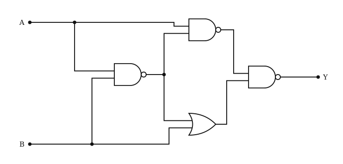
Let P=AB.
00: P=1, NAND 2 =1, OR =1, Y=0.
01: P=1, NAND 2 =1, OR =1, Y=0.
10: P=1, NAND 2 =0, Y=1.
11: P=0, NAND 2 =1, OR =1, Y=0.
Y=1 only for A=1,B=0: Y=AB.
Reading this solution needs no sign-in. You only sign in to practise against the clock and keep your progress.
Practise this with a timer