Practice portal › Semiconductor Electronics › Digital Electronics and Logic Gates
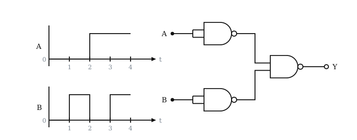
For the logic circuit shown, the output waveform at Y is [Figure: A is 0 from 0 to 2 and 1 from 2 to 4. B is 1 from 1 to 2 and from 3 to 4, 0 otherwise. A and B each go into a NAND gate with tied inputs; the two outputs feed a NAND gate giving Y. Options: (a) 1 from 0 to 1 only; (b) 1 throughout; (c) 0 throughout; (d) 0 from 0 to 1 and 1 from 1 to 4.]
Asked in JEE Main 8th April 1st Shift 2023 · Waveforms, switches and diode gates
- (1) 1 from 0 to 1 only
- (2) 1 throughout
- (3) 0 throughout
- (4) 0 from 0 to 1, then 1 from 1 to 4
Answer: (4) 0 from 0 to 1, then 1 from 1 to 4
Step-by-step solution
Tied NANDs invert: A, B. Then Y=AB=A+B.
0 to 1: A=B=0, Y=0.
1 to 2: B=1. 2 to 4: A=1. So Y=1 from 1 to 4.
Why the other options are wrong
- (1) This is NOR of the inputs.
- (2) Misses the interval 0 to 1 where both inputs are 0.
- (3) The OR output is 1 whenever either input is 1.
Reading this solution needs no sign-in. You only sign in to practise against the clock and keep your progress.
Practise this with a timer