Practice portal › Semiconductor Electronics › Zener Diode as a Voltage Regulator
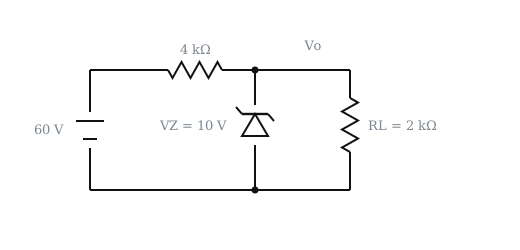
A Zener diode is connected to a battery and a load as shown below. The currents I, I_Z and I_L are respectively [Figure: a 60 V battery, 4 kΩ in series to node A, a Zener (V_Z=10 V) from A to B, and R_L=2 kΩ in parallel with it.]
Asked in JEE Main Online 2014 · Zener current and series resistance
- (1) 15 mA, 5 mA, 10 mA
- (2) 15 mA, 7.5 mA, 7.5 mA
- (3) 12.5 mA, 5 mA, 7.5 mA
- (4) 12.5 mA, 7.5 mA, 5 mA
Answer: (4) 12.5 mA, 7.5 mA, 5 mA
Step-by-step solution
I=(60-10)/(4 kΩ)=12.5 mA
I_L=(10)/(2 kΩ)=5 mA
I_Z=12.5-5=7.5 mA
Why the other options are wrong
- (1) Uses 60/4 for I, ignoring V_Z.
- (2) Uses 60/4 and splits equally.
- (3) Swaps I_Z and I_L.
Reading this solution needs no sign-in. You only sign in to practise against the clock and keep your progress.
Practise this with a timer