Practice portal › Semiconductor Electronics › Semiconductor Diode and Diode Circuits

In the given figure, each diode has a forward bias resistance of 30 Ω and infinite resistance in reverse bias. The current I₁ will be [Figure: three parallel branches, each a diode and 130 Ω; the top two diodes point in the direction the battery drives current, the bottom diode points the opposite way. The branches are fed by a 200 V battery in series with 20 Ω; I₁ is the battery current.]

Asked in JEE Main 1st Sept 2nd Shift 2021 · Circuits with diodes
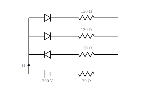
Figure: Circuits with diodes
Answer: (1) 2 A

Step-by-step solution

Two diodes are forward biased, one is reverse biased (open).

Each conducting branch: 30+130=160 Ω. Two in parallel: 80 Ω.

Total: 80+20=100 Ω

I₁=(200)/(100)=2 A

Why the other options are wrong

More Semiconductor Diode and Diode Circuits questionsAll Semiconductor Diode and Diode Circuits questions →

Reading this solution needs no sign-in. You only sign in to practise against the clock and keep your progress.

Practise this with a timer