Practice portal › Semiconductor Electronics › Diode as a Rectifier

In the circuit shown here, assuming threshold voltage of diode is negligibly small, then voltage V_AB is correctly represented by [Figure: an AC source V=V₀ sin ω t on the left; the top wire goes to terminal A; a resistor R is connected between the top wire and the bottom wire; the bottom wire from the source passes through a diode pointing right (towards B) and ends at terminal B. Options: (a) only negative half-cycles of V_AB, zero in between; (b) only positive half-cycles, zero in between; (c) a full sine wave; (d) V_AB zero at all times.]

Asked in JEE Main 28th Jan 2nd Shift 2025 · Output waveforms
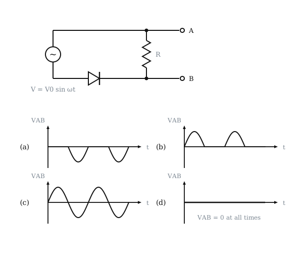
Figure: Output waveforms
Answer: (1) Only the negative half-cycles of V_AB appear, zero in between

Step-by-step solution

The diode in the lower wire lets current flow only from the source's lower terminal towards B, then up through R to A.

That happens when the lower source terminal is positive, i.e. during the negative half-cycles of V.

Current then flows from B to A through R, so B is higher than A and V_AB is negative.

In the positive half-cycles the diode blocks, no current flows and V_AB=0.

So V_AB shows only negative half-cycles.

Why the other options are wrong

More Diode as a Rectifier questionsAll Diode as a Rectifier questions →

Reading this solution needs no sign-in. You only sign in to practise against the clock and keep your progress.

Practise this with a timer