Practice portal › Current Electricity › Cells, EMF and Internal Resistance

The reading in the ideal voltmeter (V) shown in the given circuit diagram is [Figure: a single closed loop of eight identical cells, each of emf 5 V and internal resistance 0.2 Ω, all connected positive to negative in the same sense around the loop (three on the top side, one on the left side, three on the bottom side, one on the right side). The ideal voltmeter is connected directly across the terminals of the single cell on the right side.]

Asked in JEE Main 1st Feb 1st Shift 2024 · Combination of cells
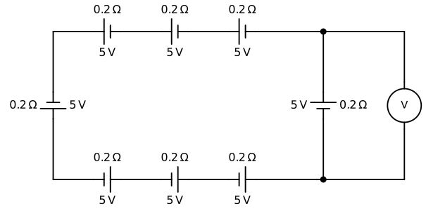
Figure: Combination of cells
Answer: (2) 0 V

Step-by-step solution

Total emf =8×5=40 V; total resistance =8×0.2=1.6 Ω.

I=(40)/(1.6)=25 A.

Across one cell: V=E-Ir=5-25×0.2=0.

The voltmeter reads 0 V.

Why the other options are wrong

More Cells, EMF and Internal Resistance questionsAll Cells, EMF and Internal Resistance questions →

Reading this solution needs no sign-in. You only sign in to practise against the clock and keep your progress.

Practise this with a timer