Practice portal › Current Electricity › Kirchhoff's Laws and Circuit Analysis
Asked in GSEB Board July 2018 · Ammeters and voltmeters in circuits
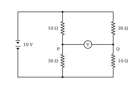
Given (figure): an ideal 10 V battery across two branches. Left branch: 10 Ω above 30 Ω, meeting at P. Right branch: 30 Ω above 10 Ω, meeting at Q. The voltmeter joins P and Q.
Idea: the voltmeter's resistance is very high, so it draws no current, and each branch is a simple potential divider across 10 V.
Current in each branch: I = (10)/(10 + 30) = 0.25 A.
With the negative terminal at 0 V, V_P = 0.25×30 = 7.5 V and V_Q = 0.25×10 = 2.5 V.
Voltmeter reading: V_P - V_Q = 7.5 - 2.5 = 5 V.
Reading this solution needs no sign-in. You only sign in to practise against the clock and keep your progress.
Practise this with a timer